Overall structural analysis of the engine


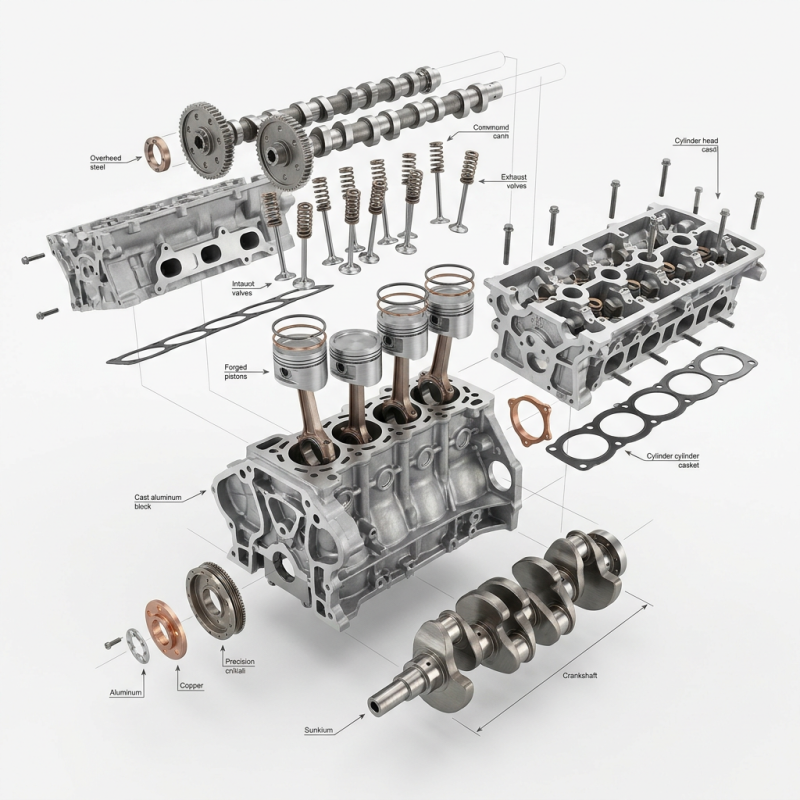
From a holistic engineering perspective, the overall structure of an engine is not simply a collection of parts, but a highly integrated composite of a thermodynamic pressure vessel and a precision motion conversion mechanism. Its architecture can be macroscopically divided into stationary engine components, reciprocating motion mechanisms, and five major auxiliary systems that ensure continuous energy conversion. The core logic of this structural design lies in maintaining micron-level motion precision while withstanding dozens of high-temperature, high-pressure impacts per second. Taking industrial-grade diesel engines (such as common 3.3-liter or 4.4-liter power platforms) as an example, their “skeleton” consists of a high-strength cylinder block, cylinder head, and oil pan. These stationary components not only provide precise physical positioning for all moving parts but also achieve closed-loop circulation of coolant and lubricating oil through complex internally cast channels, ensuring that the thousands of degrees of heat generated during fuel combustion do not cause thermal creep failure of the materials.
Power Core: The Physical Logic of the Reciprocating Motion Mechanism
The heart of the engine’s kinetic energy conversion consists of the piston assembly, connecting rod assembly, and crankshaft flywheel assembly. This mechanism completes the essential transition from linear impact to rotational torque. When fuel explodes in the combustion chamber, the piston crown directly bears the enormous pressure of the expanding gases (up to hundreds of atmospheres in high-performance engines), transferring the impulse to the connecting rod via the piston pin. The connecting rod, acting as an energy transfer bridge, acts on the crankshaft’s crankpin at its large end, using leverage to drive the crankshaft’s rotation. To counteract the enormous inertial forces generated by the reciprocating motion, a counterweight is precision-cast or forged on the crankshaft, working in conjunction with the flywheel’s rotational inertia to smooth torque fluctuations and ensure smooth power output. This process places extremely high demands on the fatigue strength of the materials; pistons are typically made of aluminum alloy with internal cooling oil passages, while the crankshaft must undergo induction hardening or nitriding to prevent fracture under high-frequency alternating stress.
Valve Train and Power Supply: Precisely Timed Breathing Logic
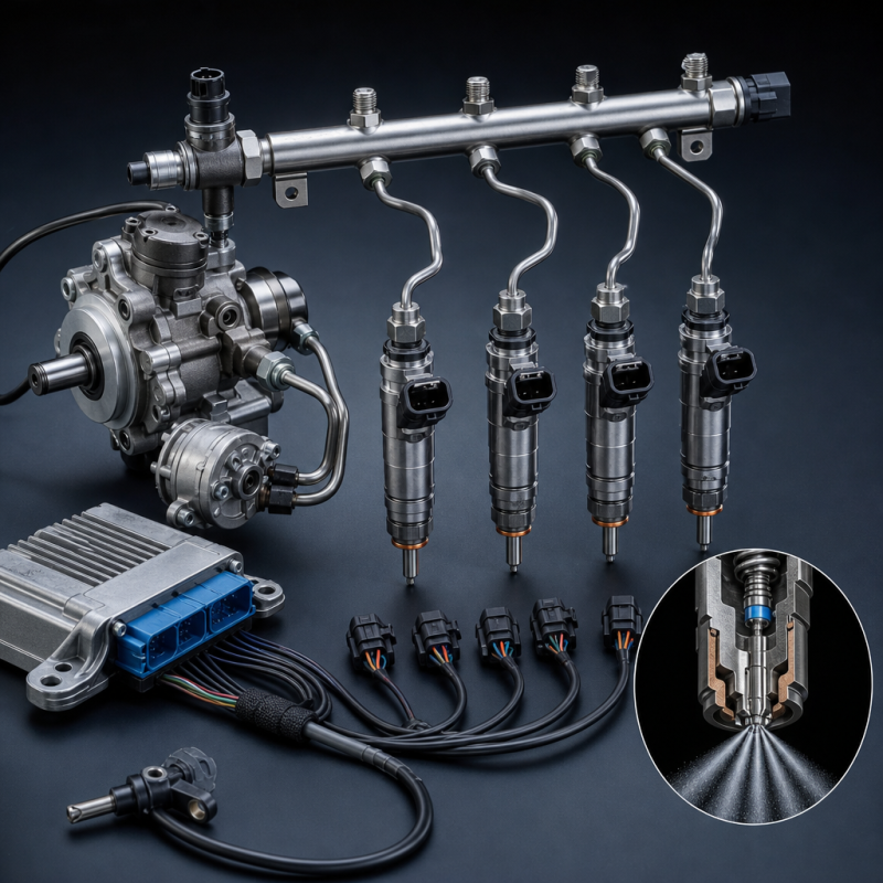
The engine’s efficiency ceiling is determined by its “breathing and power supply” system, namely the valve train and fuel system. The valve train (composed of the camshaft, tappets, rocker arms, and valves) controls the intake and exhaust of the cylinders like a precise clock. The camshaft profile determines the valve lift and duration, directly affecting cylinder charging efficiency. For industrial engines, to achieve structural stability, a gear-driven, low- or mid-mounted camshaft design is often used. Simultaneously, the fuel system—whether a traditional mechanical rotary pump or a modern high-pressure common rail system—must inject fuel as a mist into high-pressure air in a very short time at the end of the compression stroke. This injection pressure typically far exceeds 1000 bar, aiming to achieve nanoscale fragmentation of fuel molecules, thereby ensuring sufficient contact with oxygen molecules within microseconds and guaranteeing complete release of chemical energy.
Lifespan Maintenance: Thermal Balance of Lubrication and Cooling Systems
The continuous operation of an engine depends on the thermodynamic safety boundaries provided by the lubrication and cooling systems. The lubrication system, through an oil pump, delivers pressurized oil to every friction pair surface (such as main bearings, connecting rod bearings, and camshaft bushings), establishing an oil film only a few micrometers thick using the principle of hydrodynamic lubrication. This oil film not only prevents direct metal-to-metal contact friction but also undertakes the additional task of dissipating heat from the piston base and sealing cylinder pressure. Meanwhile, the cooling system uses a water pump to drive the coolant to flow at high speed in the heat exchange channels around the cylinder liners, utilizing the liquid’s high specific heat capacity to absorb excess heat energy emitted during combustion. According to the thermodynamic efficiency formula $\eta = 1 – \frac{T_{low}}{T_{high}}$, the engine can only convert about 35%-45% of the heat into mechanical work. The remaining energy must be dissipated into the atmosphere in a timely manner through these two systems; otherwise, internal parts will seize up within minutes due to thermal expansion exceeding clearance limits.
jianming machinery