Turbocharging Technology for Diesel Engines


The core of diesel engine turbocharging technology lies in utilizing energy that would otherwise be lost in the exhaust stream to drive a turbine. This turbine, in turn, powers a coaxial compressor that compresses fresh intake air, thereby increasing the cylinder charge without requiring a significant increase in engine displacement. A turbocharger primarily consists of a turbine, a compressor, a central shaft, floating bearings, and a bearing housing. High-temperature exhaust gases enter the turbine housing and drive the turbine wheel, which causes the compressor wheel to spin at high speeds; this draws in ambient air, compresses it, and delivers it to the cylinders. Because the compression process raises the air temperature—which reduces the density gain—modern turbocharged diesel engines are typically equipped with an intercooler. This cools the compressed air before it enters the intake manifold, ensuring a higher oxygen content per unit volume. With a greater mass of air in the cylinders, the engine can inject more fuel while maintaining an optimal air-fuel ratio, resulting in increased torque, higher power density, and better performance retention at high altitudes. Furthermore, an ample air supply helps prevent localized overly rich combustion, thereby suppressing the formation of black smoke and particulate matter. However, higher boost pressure is not always better; excessive pressure increases peak cylinder combustion pressure, exhaust temperatures, and the thermal load on the pistons. It can also lead to issues such as compressor surge, turbine overspeed, and damage to the cylinder head gasket. Consequently, boost pressure must be carefully balanced with fuel injection quantities, the structural integrity of the engine, and its cooling capacity.
The primary technical challenge in turbocharging systems is balancing the competing requirements for low-speed response, high-speed airflow, and efficiency across the entire operating range. Conventional fixed-geometry turbochargers are simple and durable; however, at low engine speeds, the available exhaust energy is often insufficient to spin up the turbine quickly, leading to “turbo lag.” Conversely, if the turbine’s flow cross-section is reduced to improve low-speed torque, it may result in excessive exhaust backpressure and turbine overspeed at high engine speeds. Variable-geometry turbochargers (VGTs) adjust the exhaust flow area by varying the angle of the nozzle ring vanes: at low speeds, the flow passages are narrowed to increase exhaust gas velocity and accelerate the build-up of boost pressure; at high speeds and high loads, the passages are widened to reduce exhaust backpressure and limit the turbocharger’s rotational speed. Two-stage turbocharging systems utilize both a high-pressure stage and a low-pressure stage, enabling the engine to achieve a higher pressure ratio and stable airflow across a broader speed range—a configuration well-suited for high-power-density diesel engines. Series-configured systems prioritize high pressure ratios, while parallel-configured systems are better adapted for engines with large displacements and multiple cylinders, where exhaust streams can be grouped. Electrically assisted turbochargers use an electric motor to rapidly drive the compressor or turbine shaft, further enhancing transient response; however, their application is constrained by factors such as the power capacity of the electrical system, cost, and thermal management requirements. Regardless of the chosen configuration, the compressor and turbine characteristics must be carefully selected based on engine displacement, target power output, typical operating speed range, exhaust flow rate, and altitude conditions to ensure that the operating point does not fall within the surge, choke, or overspeed regions.
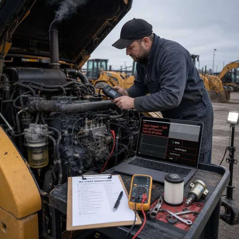
Turbochargers are highly dependent on proper lubrication, cooling, intake/exhaust sealing, and correct operational practices. Because the turbocharger shaft operates under conditions of extreme speed and high temperature, the bearings rely on engine oil to form a stable lubricating film. Consequently, issues such as insufficient oil pressure, blocked oil passages, oil contamination, or incorrect oil viscosity can lead to journal wear, increased radial clearance, or even rotor seizure. A clogged air filter increases the negative pressure at the compressor inlet, raising the risk of engine oil leaking past the seals into the intake tract. Leaks in the intake piping result in an actual air intake volume that falls short of the target, manifesting as a loss of power, increased black smoke, and insufficient boost pressure. Conversely, leaks in the exhaust manifold or the piping upstream of the turbine result in a loss of driving energy, causing sluggish turbine response. When diagnosing issues, one should conduct a comprehensive assessment—evaluating target versus actual boost pressure, intake airflow, exhaust backpressure, turbocharger rotational speed, and inlet/outlet temperatures—rather than concluding that a turbocharger is damaged simply because a small trace of oil is found in the piping. If you observe abnormal whistling, the impeller rubbing against the housing, a significant increase in axial clearance, excessive oil leakage, or persistent blue exhaust smoke, you should inspect the condition of the impeller, bearings, and oil return line. During daily operation, avoid running the engine under high load immediately after a cold start; likewise, do not shut down the engine immediately after heavy-duty operation—this allows the engine oil to continue carrying heat away from the bearing housing and prevents high-temperature coking. When replacing a turbocharger, also clean the oil supply line, oil return line, intercooler, and intake piping. Furthermore, identify the root cause of the original unit’s failure; otherwise, residual debris, accumulated oil, or issues with the oil supply system could cause the new turbocharger to fail as well.
jianming machinery