Turbocharger System Fault Diagnosis: Analysis of Failure Mechanisms Ranging from Fluid Lubrication and Pressure Balance to Overall System Matching

In modern diesel engines, the turbocharger has become a crucial component for enhancing volumetric efficiency, improving combustion quality, and meeting emission regulations. Across applications ranging from construction machinery and mining equipment to commercial trucks and diesel generator sets, the turbocharger’s operating condition not only determines engine power output but also directly impacts fuel economy, emission levels, and overall system reliability.
However, in practical maintenance scenarios, the turbocharger is frequently misdiagnosed. Numerous field cases reveal that many turbochargers replaced due to issues like power loss, excessive oil consumption, or abnormal boost pressure show no significant mechanical damage; the actual root causes often lie in anomalies within the lubrication system, intake and exhaust systems, crankcase ventilation system, or electronic control system.
Therefore, diagnosing turbocharger faults should not be limited to the impeller, bearings, or housing itself; instead, a systematic analysis is required, considering the engine’s overall gas flow, lubrication circulation, and pressure balance.
I. The Turbocharger: A High-Speed Fluid Machinery System
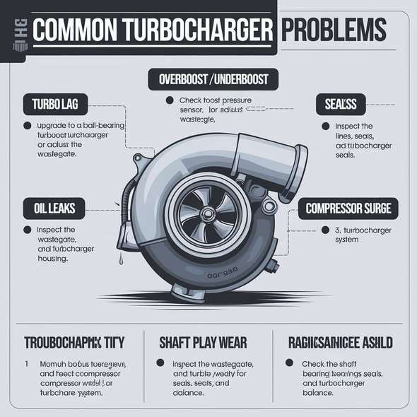
Structurally, a turbocharger consists of a turbine section, a compressor section, and a central bearing housing.
High-temperature, high-pressure exhaust gas from the exhaust manifold drives the rotation of the turbine wheel. Through a rigid shaft, this rotation drives the compressor wheel, compressing air and delivering it to the intake manifold to boost the engine’s volumetric efficiency.
The rotor system is the component that truly endures these extreme operating conditions.
Modern diesel turbochargers typically reach rotational speeds of 150,000 to 250,000 rpm, with some small-displacement, high-boost engines exceeding 300,000 rpm. Simultaneously, exhaust temperatures at the turbine inlet consistently range from 700°C to 900°C, potentially exceeding 950°C during transient operations.
Under such demanding conditions, the shaft is not supported by rolling-element bearings; instead, it achieves complete suspension through a hydrodynamic oil film only a few micrometers thick.
In other words, the component truly supporting the entire rotor assembly is not the bearing itself, but a continuously established and replenished lubricating oil film. Any factor that causes a reduction in oil film thickness, insufficient oil supply, or oil contamination can rapidly cause fluid lubrication to degrade into boundary lubrication, ultimately leading to bearing wear, rotor imbalance, or even impeller contact.
II. Why most turbocharger failures are not caused by damage to the turbocharger itself
A common misconception in the field is to attribute all issues regarding insufficient power or excessive oil consumption directly to turbocharger failure.
In reality, the turbocharger is merely one component within the engine’s air intake and exhaust system; its operating condition is influenced by multiple systems.
For instance, when the air filter is severely clogged, resistance at the compressor inlet increases significantly.
As the compressor impeller continues to spin at high speed, the local static pressure at the inlet drops rapidly, creating a zone of significant negative pressure.
Even though the turbocharger’s mechanical condition remains sound, the airflow becomes clearly insufficient.
At this point, the ECU continues to inject fuel based on the driver’s load demand. Consequently, less air enters the cylinders while the diesel injection quantity remains unchanged; this lowers the air-fuel ratio and results in incomplete combustion, manifesting as:
Black exhaust smoke;
Reduced engine power;
Elevated exhaust temperatures;
Increased fuel consumption.
Simply replacing the turbocharger in this scenario fails to address the root cause of the problem.
III. Lubrication system failure is the primary cause of bearing damage
Extensive failure analysis indicates that premature turbocharger bearing damage is usually linked to deteriorating lubrication conditions rather than material fatigue.
Key causes include:
① Insufficient oil supply pressure
When oil pressure drops, the floating bearings cannot establish a stable oil film.
Micro-contact friction occurs between the shaft and bearings, causing bearing temperatures to rise rapidly.
② Lubricating oil contamination
The entry of metal particles, carbon deposits, and sludge into the bearing clearances disrupts the fluid lubrication state.
As abrasive wear accumulates, bearing clearances gradually increase.
③ Heat soak
Shutting down the engine immediately after heavy-load operation is a major factor in shortening turbocharger lifespan.
Oil circulation ceases the moment the engine stops.
However, the high-temperature turbine housing continues to conduct heat into the bearing housing. Localized engine oil undergoes thermal cracking due to prolonged stagnation, resulting in carbon deposits.
These deposits not only clog oil supply ports but also disrupt the formation of the oil film during the next startup.
Therefore, for construction machinery operating under high loads for extended periods, it is recommended to idle the engine for 2–3 minutes before shutdown to allow exhaust gas and bearing housing temperatures to gradually decrease.
IV. Oil consumption does not necessarily indicate seal failure
Many technicians assume a turbocharger has a “damaged oil seal” simply upon seeing oil in the compressor or exhaust pipe.
In reality, modern turbochargers do not contain traditional rubber oil seals.
Sealing relies on:
Piston ring seals;
Pressure differential balance;
Unobstructed oil drainage.
When crankcase pressure rises or oil drainage is obstructed, the oil pressure inside the bearing housing continues to increase.
In such cases, lubricating oil may still enter the compressor or turbine sections, even if the sealing mechanism is functioning perfectly.
Therefore, before diagnosing an oil leak, the following should be measured:
Crankcase pressure;
Pressure loss in the oil drain line;
Breather operating status;
Compliance of the oil drain slope with specifications.
Only after ruling out system-related issues should one proceed to determine if the turbocharger has sustained mechanical damage.
V. Establish a systematic diagnostic process
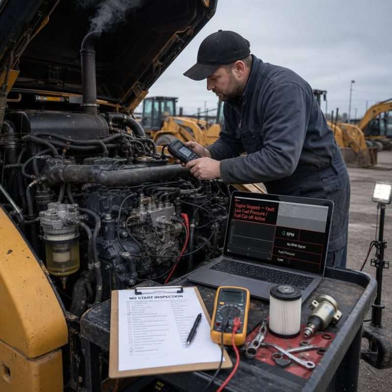
Turbocharger diagnostics should follow the principle of proceeding “from outside to inside” and “from system to component.”
It is recommended to conduct inspections in the following order:
Step 1: Inspect the air intake system
Check air filter restriction, intercooler leakage, and the sealing of boost piping.
Step 2: Inspect the lubrication system
Measure oil pressure; check oil supply lines, drain lines, and oil quality.
Step 3: Inspect the crankcase ventilation system
Measure crankcase pressure; verify proper breather operation; rule out oil drainage obstructions.
Step 4: Inspect mechanical condition
Measure rotor axial and radial clearances; inspect impellers for signs of rubbing or foreign object damage.
Step 5: Inspect the electronic control system
Read ECU fault codes; perform dynamic testing on the VGT actuator, wastegate, and pressure sensors.
Only after completing these system checks can one accurately determine whether the turbocharger requires repair or replacement. Conclusion
A turbocharger is essentially a high-speed rotating machine operating under extreme thermodynamic and fluid-dynamic conditions; its performance depends not only on its own structural design but also on the coordinated operation of the lubrication, intake and exhaust, crankcase ventilation, and electronic control systems. Field maintenance experience demonstrates that truly effective fault diagnosis relies not on empirical judgment alone, but on comprehensive analysis grounded in system pressure assessment, fluid lubrication theory, and engine matching characteristics.
For modern diesel engines, adhering to the maintenance philosophy of “systems before components, diagnosis before replacement” not only improves the efficiency of fault localization but also effectively prevents redundant repairs and the unnecessary replacement of parts, thereby reducing the equipment’s total lifecycle maintenance costs.
jianming machinery