Thermal Management Engineering for Diesel Engines Under High-Load Conditions: Thermodynamic Coupling and Optimization of Overall Engine Reliability


In heavy-duty sectors such as construction machinery and high-power generator sets, modern diesel engines frequently operate under sustained high loads and harsh environmental conditions. With the widespread adoption of technologies like high-pressure common-rail fuel injection, variable geometry turbocharging (VGT), exhaust gas recirculation (EGR), and diesel particulate filters (DPF), specific power output and mechanical power density have risen sharply, leading to an exponential increase in the engine’s overall thermal load.
Under these operating conditions, thermal management transcends simple coolant temperature control; it has become a comprehensive system engineering discipline integrating engineering thermodynamics, fluid dynamics, and tribology. The ability to efficiently manage and dissipate the thermal energy generated by fuel combustion—and to achieve a synergistic thermal balance among the cylinder head, piston assembly, turbocharger, and exhaust after-treatment system—directly determines the engine’s power output stability, full-lifecycle reliability, and fuel economy.
I. Thermodynamic Energy Distribution and Sources of Additional Thermal Loads
According to the First Law of Thermodynamics, only 40% to 50% of the total chemical energy released during diesel fuel combustion is converted into effective crankshaft work, while more than half of the remaining energy transforms into waste heat. During sustained high-load operation, the generation of this waste heat is characterized by multiple sources and high-density concentration:
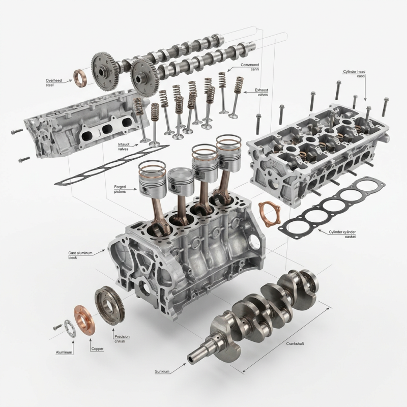
High Heat Flux in the Combustion Chamber: Rapid, violent combustion within the chamber causes instantaneous temperatures to soar to several thousand degrees Celsius. Intense heat is transferred via convection and radiation from the hot gas stream to the piston crown, cylinder liner, and cylinder head deck. The “bridge” area of the cylinder head (located between the exhaust valve seat and the fuel injector bore) and the piston crown become the zones where thermal stress is most concentrated and where thermal fatigue cracking is most likely to occur.
Frictional Shear Heat Under High Speed and Load: Mechanical friction losses occur at the crankshaft main bearings, connecting rod bearings, and the interface between piston rings and cylinder liner walls, all within an environment of sustained high heat generation. Exhaust Energy Recovery and Turbocharger Heat Soak: Under high-load conditions, exhaust enthalpy rises significantly; this not only radiates substantial thermal energy outward but also directly heats the turbine housing and bearing housing (center housing) of the exhaust gas turbocharger.
Emission After-treatment and Thermal Feedback: High-temperature exhaust gas introduced by the high-pressure EGR system places an additional cooling load on the cooling system. Meanwhile, during active DPF regeneration, exhaust temperatures are forced above 600°C, subjecting the downstream exhaust components to severe thermal shock.
If this waste heat is not dissipated promptly and effectively via the cooling and lubrication systems, thermal deformation of components can compromise original design clearances, leading to localized dry friction, degradation of material mechanical strength, or even catastrophic failure.
II. System Coupling of Cooling and Lubrication: A Dual Thermal Defense
In the thermal management architecture of high-load diesel engines, the cooling and lubrication systems function as a deeply coupled, synergistic “dual-core” system. In actual operation, the lubrication system handles 20% to 30% of the engine’s total heat dissipation requirements.
- Cooling System Temperature Window and Cavitation Control
For medium-to-large heavy-duty diesel engines, the ideal steady-state coolant temperature is strictly maintained within the 85–95°C range:
Low-temperature conditions (<80°C): Cylinder wall temperatures are too low, delaying fuel atomization and evaporation; this promotes the formation of a condensed oil film on the cylinder wall, which washes away the lubricating oil. Simultaneously, excessive lubricating oil viscosity leads to a sharp increase in pumping resistance and mechanical friction losses.
High-temperature conditions (>100°C): Localized volumetric efficiency at the cylinder head is significantly inhibited, resulting in insufficient intake air and localized fuel-rich combustion. More critically, overheating causes the collapse of microscopic bubbles against the outer wall of the cylinder liner, triggering severe cavitation erosion that can ultimately lead to liner perforation and coolant leakage. 2. The role of lubricating oil as a “micro-scale liquid cooling medium”
For internal cavities not covered by the cylinder liner’s cooling water channels, forced heat exchange must be achieved through engine oil:
Piston oil-cooling technology: Modern high-power diesel engines typically feature piston cooling jets (PCJs) located beneath the engine block. These continuously spray oil into the cooling channels within the piston cavity, directly transporting heat from the piston crown back to the oil sump.
Shear-resistant bearing oil film: Under conditions of high temperature and heavy load, the hydrodynamic oil film between the crankshaft and the bearing shell is prone to thinning as temperatures rise. Selecting oil based solely on room-temperature viscosity is insufficient for such harsh operating conditions; instead, the oil’s High-Temperature High-Shear (HTHS) viscosity stability is crucial to resist fluid shear and prevent bearing shell ablation caused by boundary lubrication.
III. Discussion on extreme thermal conditions: The turbocharger “heat soak effect”
During heavy-duty operations, the turbocharger operates in an extremely demanding environment: the rotor assembly spins at speeds exceeding 200,000 rpm, and exhaust gas temperatures at the turbine inlet consistently range from 700°C to 900°C. Dynamic support, lubrication, and heat dissipation rely entirely on a micron-scale flowing oil film within the floating bearings.
Among the technical risks associated with high-load operation, the “heat soak effect” is particularly destructive. If the engine is shut down abruptly after prolonged full-load operation, the oil pump stops instantly, cutting off the flow of pressurized oil and cooling water. Consequently, the immense heat accumulated in the exhaust manifold and turbine housing cannot be carried away by circulating fluids; instead, it surges back into the central bearing housing via inward conduction and thermal radiation.
This rapid temperature spike can momentarily exceed the oil’s thermal tolerance limits. Residual oil trapped within the floating bearings and oil seal cavities undergoes rapid thermal cracking and high-temperature oxidation, eventually coking to form hard carbon particles and varnish deposits. This carbon buildup not only disrupts the rotor’s dynamic balance but also gradually narrows or even completely blocks the fine lubricating oil passages. This can lead to bearing seizure or scoring due to momentary lubrication failure during subsequent cold starts or high-load operations, ultimately resulting in the total destruction of the turbocharger assembly.
Therefore, after operating under heavy loads or continuous uphill driving, the engine must idle without load for 2 to 3 minutes. This allows the exhaust temperature to stabilize and drop to a safe range before the engine is fully shut down.
IV. Core Maintenance Protocols and Engineering Preventive Measures
To ensure the thermal management system remains in optimal physical condition, strict technical standards must be established for the engineering maintenance of cooling systems and lubrication circuits.
- Radiator Thermal Resistance Optimization and Airflow Path Clearing
Construction machinery and mining equipment often operate in environments rife with dust and airborne debris. Clogging of the radiator core fins not only reduces the effective frontal area but also—through the mixture of dust and oil—creates an “insulating layer” with extremely low thermal conductivity on the metal fin surfaces.
Operational Guideline: Low-pressure compressed air or a low-pressure water jet must be used to perform reverse, perpendicular purging from the leeward side to the windward side of the radiator. The use of high-pressure water jets at close range or at an angle is strictly prohibited; such actions could cause widespread bending or deformation of the aluminum cooling fins, leading to a permanent increase in airflow resistance.
- Control of Coolant Quality and Scaling-Induced Thermal Resistance
In heat exchange systems, scale buildup is the primary enemy of thermal efficiency. Calcium carbonate scale has a thermal conductivity of only 0.8–1.2 W/(m·K)—less than one-fiftieth that of cast iron. A scale layer just 0.5 mm thick on the outer wall of a cylinder liner is sufficient to cause a localized temperature spike of 30–50°C in the liner.
Operational Guideline: It is strictly prohibited to replenish the system with unsoftened tap water or groundwater. Organic Acid Technology (OAT) antifreeze—which offers cavitation and corrosion resistance—must be replaced according to the specified service intervals. This protects cylinder liner walls from the impact of collapsing micro-bubbles and prevents rust and scale formation within the cooling system.
- Engine Oil Selection Criteria Based on HTHS Viscosity
Lubricant degradation in high-temperature, high-shear environments is a primary cause of excessive wear in mechanical power systems. Prolonged exposure to high-load thermal cycling causes the polymer viscosity index improvers in the oil to break down under mechanical shear, leading to a collapse in the oil’s effective operating viscosity.
Operational Guidelines: Oil selection must strictly adhere to the API specifications and SAE viscosity grades mandated by the engine manufacturer. For long-duration, high-load operations, particular attention should be paid to the oil’s HTHS rating and oxidation stability. This prevents thermal degradation of the oil from compromising piston under-crown cooling and causing a loss of load-bearing capacity in the bearing oil film.
- Thermal Management Control Circuit Diagnostics (Thermostat and Fan Clutch)
Latent faults in mechanical or electronic thermal management components often result in chronic thermal imbalance within the engine. Issues such as thermostat sensing element aging, valve sticking, or malfunctions in the electronically controlled viscous fan clutch can directly disrupt the machine’s overall thermal management equilibrium.
Operational Guidelines: When monitoring instruments indicate intermittent overheating or sluggish cold starts, maintenance should not be limited to merely cleaning the radiator. Instead, technicians should use infrared thermometers or diagnostic tools to quantitatively compare inlet and outlet coolant temperatures, the thermostat’s full-open threshold, and the cooling fan’s rotational speed response across various temperature ranges, thereby identifying and rectifying control circuit faults at the source.
V. Technical Outlook: Evolution from Passive Mechanical Adaptation to Intelligent Thermal Management
As diesel engine thermal efficiency pushes beyond the theoretical ceiling of 50%, traditional passive water pumps (with displacement mechanically linked to crankshaft speed) and fixed cooling circuits can no longer meet the precision cooling demands of complex, variable operating conditions. Modern and next-generation heavy-duty powertrain systems are evolving toward technologies featuring “active decoupling and intelligent zonal control”:
Flow Decoupling and Active Response: Fully electronically controlled water pumps (EWPs) and variable-displacement oil pumps have completely eliminated the rigid coupling between fluid flow rates and engine speed. Even under high-risk, high-thermal-load conditions—such as a fully loaded mining truck starting off or climbing a steep grade—the management system can actively boost the speeds of the water and oil pumps to initiate proactive, full-load cooling.
Intelligent Zonal Thermal Control: Utilizing a Thermal Management Control Unit (TMCU) and multi-port proportional electronic thermostats, modern engines achieve complete decoupling of the cooling circuits for the cylinder head and the cylinder block. The system can deliver high-flow, low-temperature cooling to the cylinder head area—where preventing thermal fatigue and controlling NOx emissions are critical—while maintaining a relatively high operating temperature in the cylinder block area. This keeps the engine oil at an optimal low-viscosity state along the cylinder walls, thereby minimizing frictional losses from piston rings and pushing the engine’s thermodynamic efficiency to new heights.
jianming machinery